






IT M
IT M
Single-phase command and control transformers
Quality and versatility in low-power transformation
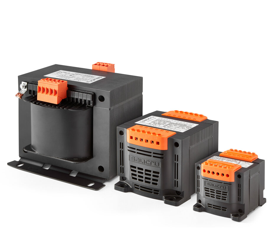
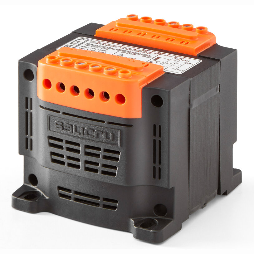
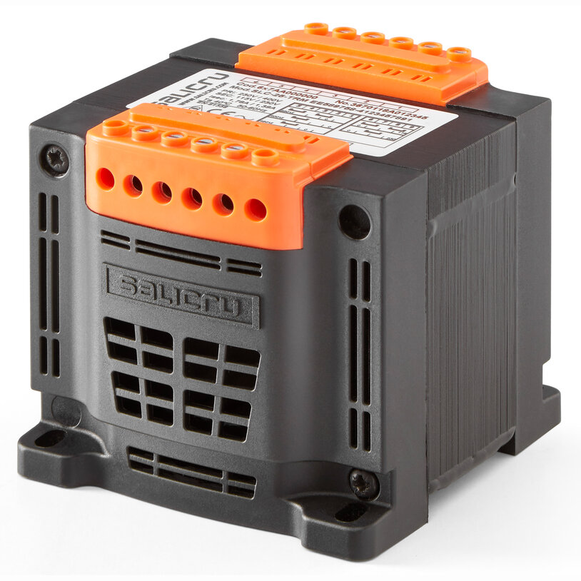
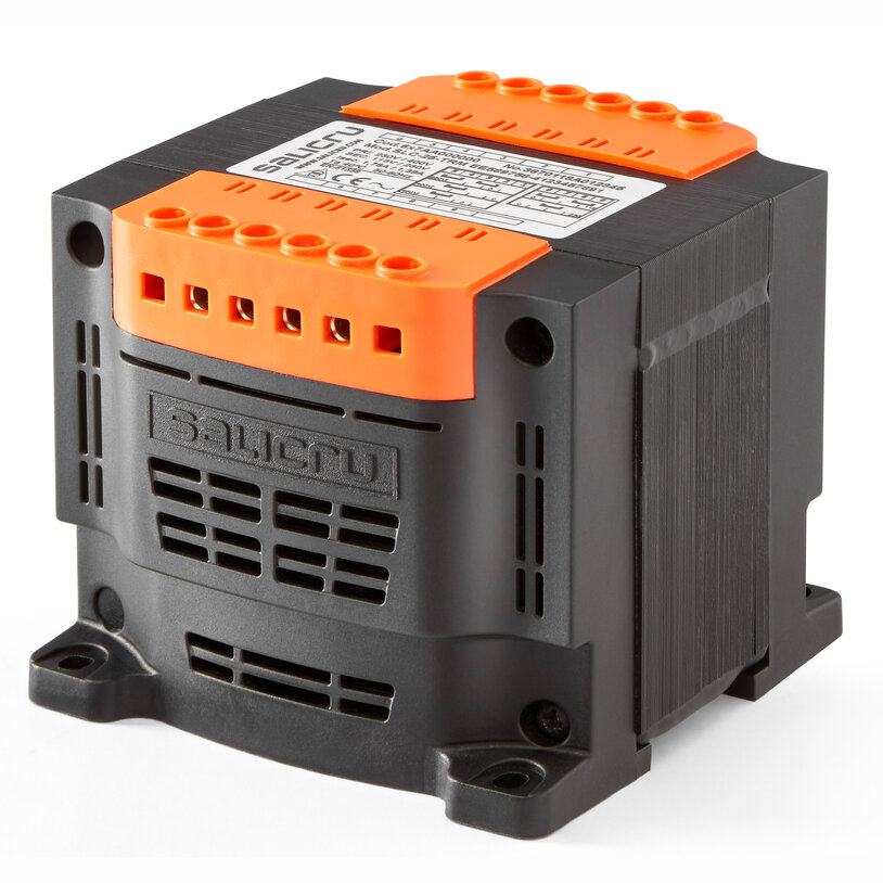
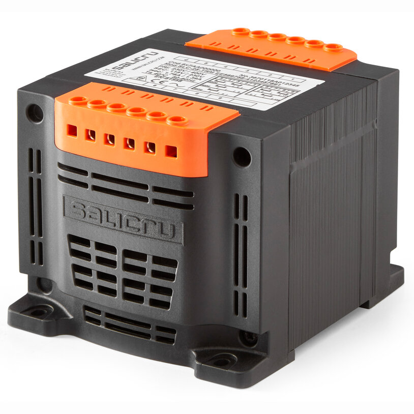
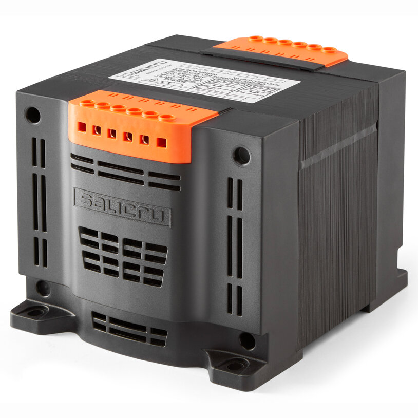
Salicru has been designing and manufacturing low-voltage electrical transformers for more than 50 years, both for use as an independent solution and as part of its wide range of power electronics solutions. The single-phase control transformers from its IT M series have been calculated and designed following the most stringent technical criteria, and tested using the most modern technologies. They are mainly used to adjust mains voltage levels and adapt them to that required by different applications in the industrial, tertiary and residential sectors.
They are also used as electrical insulation to power devices that need circuit separation, as well as to provide a safety voltage in locations that require it. The transformers from the IT M series are highly versatile thanks to their double or triple primary voltage and double secondary voltage, which is obtained by choosing between serial or parallel connection using the metal jumpers included.
Characteristics
Applications
Control, command, insulation and safety
The transformers from the IT M series fulfil four purposes required by a large variety of facilities: control, command, insulation and safety. Because of this, they can be used in many different applications in industrial, tertiary and residential sectors. They are widely used in the construction of electrical panels due to their compact size, ease of mounting and the flexibility offered by having several voltage sockets.
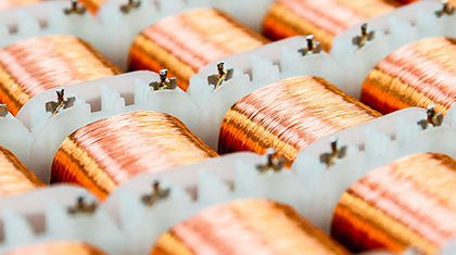
They supply a large amount of instantaneous power which enables the coils of contactors, relays, protections and other devices usually present on panels to be correctly magnetised.
Performances

IP20 protection rating

Input multi-sockets

Output multi-sockets

DIN rail mounting

Self-extinguishing housing

Compact size
Connection diagram 1
- Input iA: 230 V – 400 V
- Output oR: 12 V (V1) – 24 V (V2)
- Output oS: 24 V (V1) – 48 V (V2)
- Output oT: 115 V (V1) – 230 V (V2)

Connection diagram 2
- Input iB: 230 V – 400 V - 460 V
- Output oR: 12 V (V1) – 24 V (V2)
- Output oS: 24 V (V1) – 48 V (V2)
- Output oT: 115 V (V1) – 230 V (V2)

Connection diagram 3
- Input iB: 230 V – 400 V - 460 V
- Output oR: 12 V (V1) – 24 V (V2)
- Output oS: 24 V (V1) – 48 V (V2)
- Output oT: 115 V (V1) – 230 V (V2)

Models
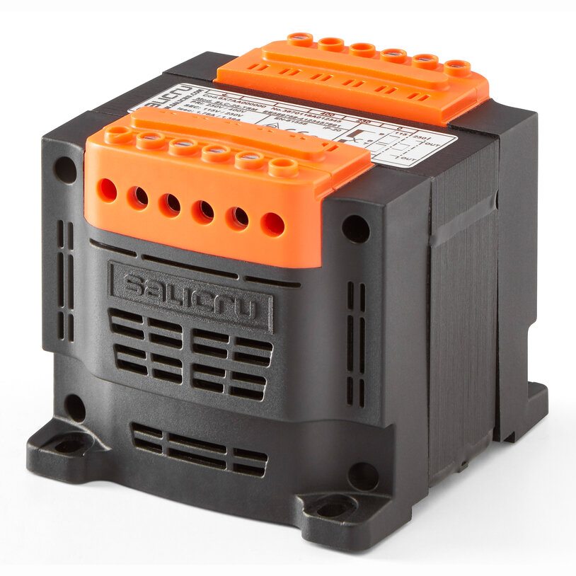
IT M-25 E iAoR
Format:
Encapsulated IP20 / Diagram 1
Input voltage (V):
230-400
Output voltage (V):
12-24
System power (VA/W):
25
Power (VA):
25 ÷ 100
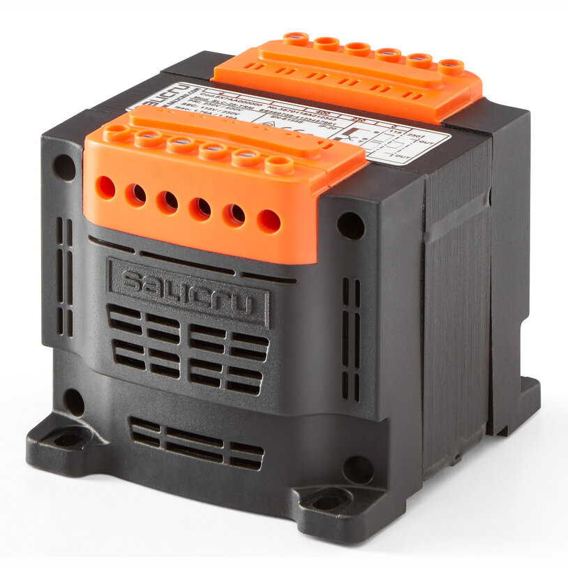
IT M-40 E iAoR
Format:
Encapsulated IP20 / Diagram 1
Input voltage (V):
230-400
Output voltage (V):
12-24
System power (VA/W):
40
Power (VA):
25 ÷ 100
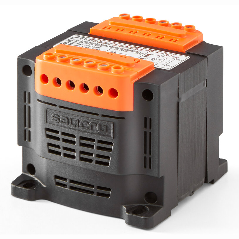
IT M-63 E iAoR
Format:
Encapsulated IP20 / Diagram 1
Input voltage (V):
230-400
Output voltage (V):
12-24
System power (VA/W):
63
Power (VA):
25 ÷ 100
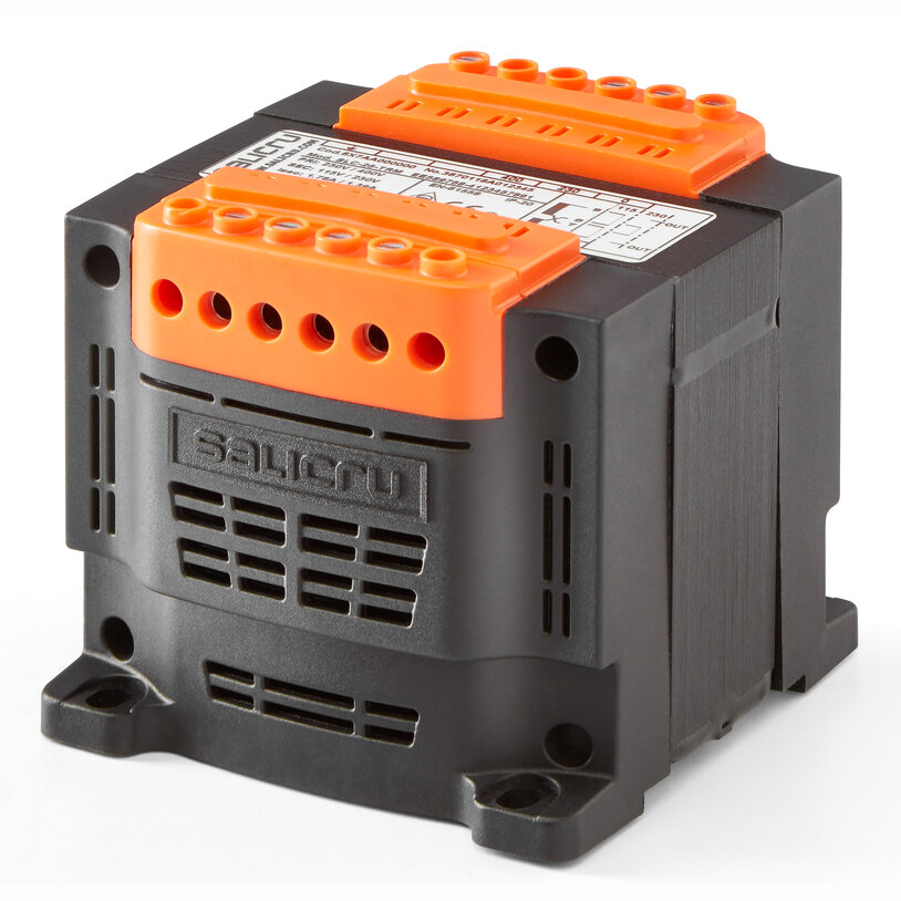
IT M-100 E iAoR
Format:
Encapsulated IP20 / Diagram 1
Input voltage (V):
230-400
Output voltage (V):
12-24
System power (VA/W):
100
Power (VA):
25 ÷ 100
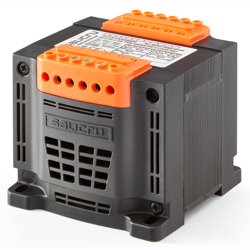
IT M-160 E iBoR
Format:
Encapsulated IP20 / Diagram 2
Input voltage (V):
230-400-460
Output voltage (V):
12-24
System power (VA/W):
160
Power (VA):
160 ÷ 800
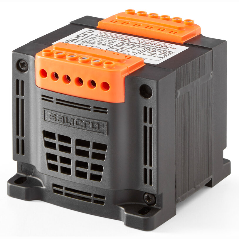
IT M-200 E iBoR
Format:
Encapsulated IP20 / Diagram 2
Input voltage (V):
230-400-460
Output voltage (V):
12-24
System power (VA/W):
200
Power (VA):
160 ÷ 800
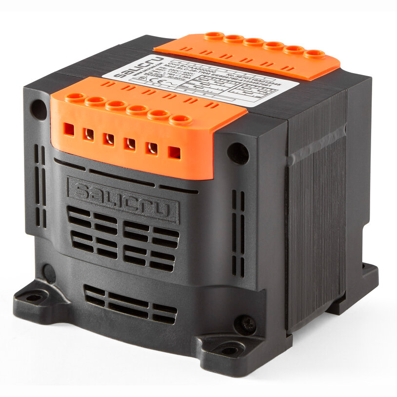
IT M-250 E iBoR
Format:
Encapsulated IP20 / Diagram 2
Input voltage (V):
230-400-460
Output voltage (V):
12-24
System power (VA/W):
250
Power (VA):
160 ÷ 800
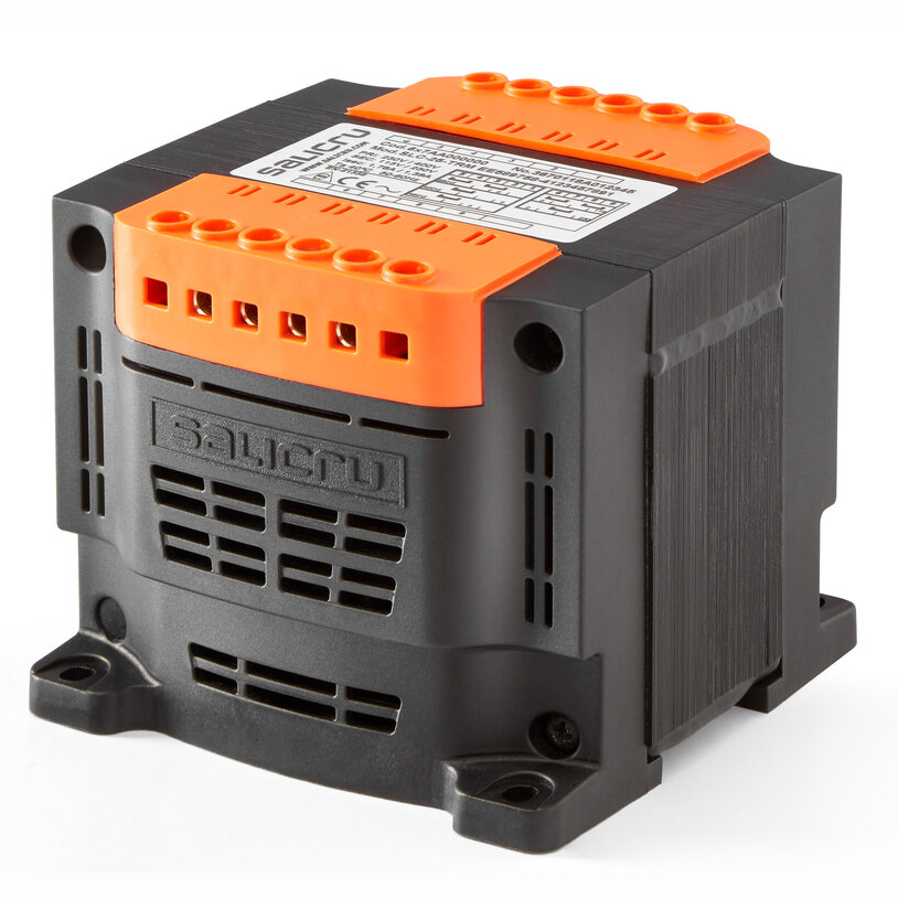
IT M-320 E iBoR
Format:
Encapsulated IP20 / Diagram 2
Input voltage (V):
230-400-460
Output voltage (V):
12-24
System power (VA/W):
320
Power (VA):
160 ÷ 800
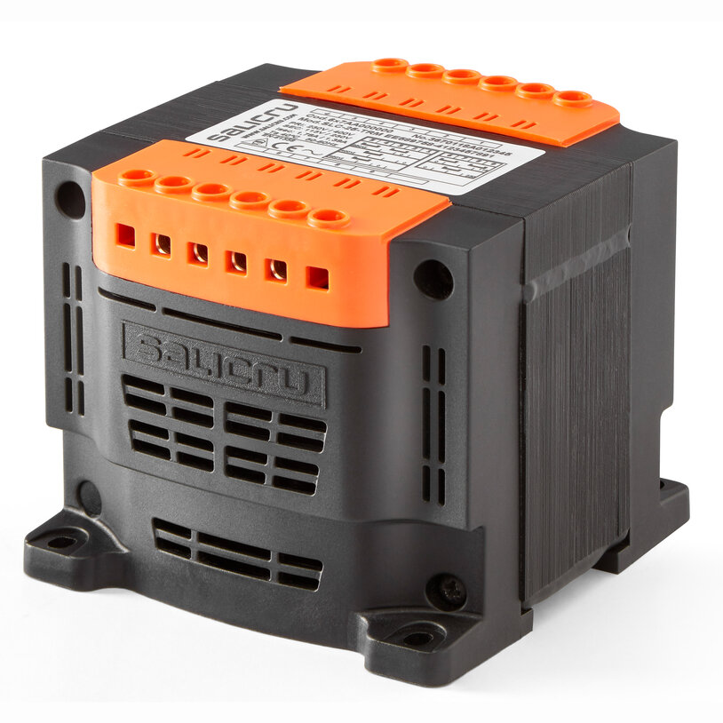
IT M-400 E iBoR
Format:
Encapsulated IP20 / Diagram 2
Input voltage (V):
230-400-460
Output voltage (V):
12-24
System power (VA/W):
400
Power (VA):
160 ÷ 800
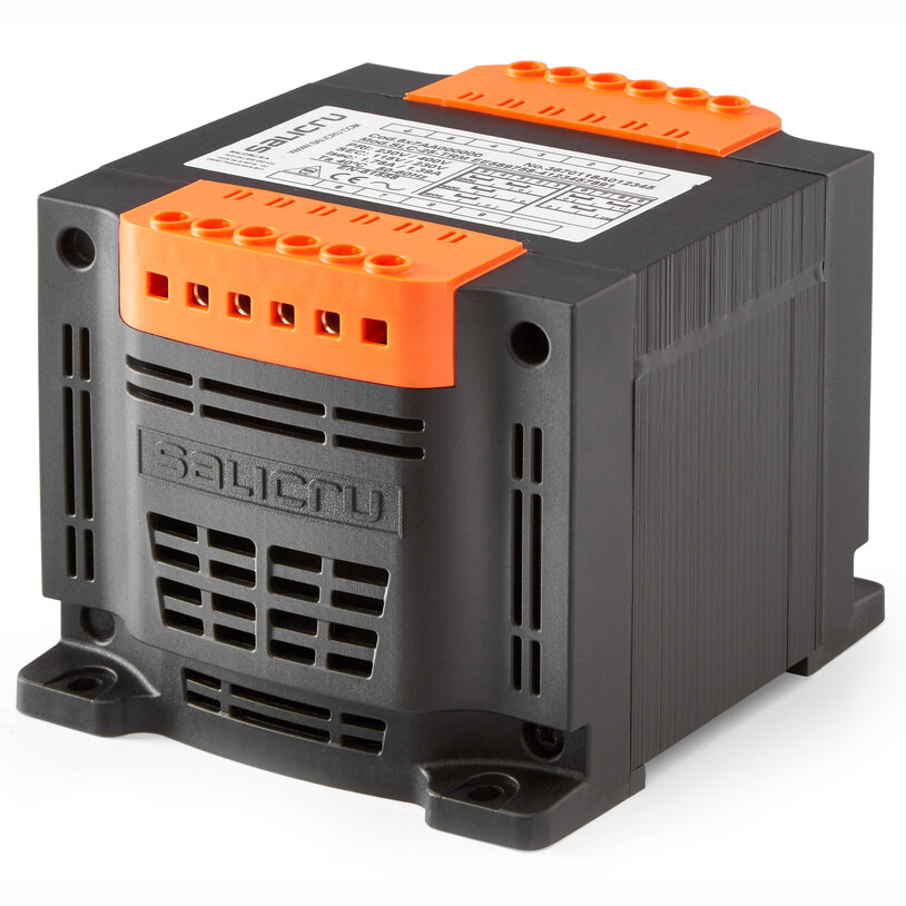
IT M-500 E iBoR
Format:
Encapsulated IP20 / Diagram 2
Input voltage (V):
230-400-460
Output voltage (V):
12-24
System power (VA/W):
500
Power (VA):
160 ÷ 800
Request information about IT M


 MONTAWEB.com